

TeleToyland Sandbox How It Works: Step 2
Step 7: Motors & Potentiometers
There are a lot of options for motors. In the previous project, we used hacked high power hobby servos. These work well for the Y axis since there is not that much mass to move. For the X axis, we switched to a DC Gearhead motor, which has been very reliable.Stepper Motors
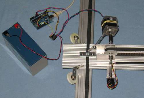
We tried using stepper motors and the ones we used were OK, but slightly under-powered for this application (for the X axis) - they were 1.2 amp ones from Pololu. Pololu also has a low-cost stepper driver carrier board that can work with them. It worked well for the Y axis, but a higher power stepper would be better for the the X axis since that 1x3 t-slot etc. is a lot of mass to move for the size of stepper motor we tried. It did work, though - just skipped a few steps now and then, until we added some acceleration to the stepper commands. So, that approach will surely work with the proper tuning of acceleration and size of motor. You'd need something like an Arduino to drive them, though (that's what we did), to make the steps. Also, you may need to add some limit switches - a bigger issue for the TeleToyland Sandbox since we would want to automatically home the robot with each sequence since it runs un-attended. All doable. Those parts together cost about $100 (steppers are ~$18, drivers are ~$13, and Arduino Uno is ~$30).
Encoders + DC Motors
We also tried using motors with encoders and a RoboClaw driver board. That also works, but the board provides PID for velocity and not position, so it wasn't as precise for this type of application as we'd hoped. They have been great for some other robot projects, though. You can definitely get more precise (expensive) position based drivers. We won't go into this too much - it's well worn material in CNC forums. As with the steppers, motors with encoders, would also need some limit switches for our application.
Potentiometers + DC Motors
In the end, we decided to use the Pololu JRK 21v3 motor controllers ($50), with motors from Lynxmotion (GHM-16 -$22) - you can get similar ones elsewhere - they are 12v 200RPM gearhead motors with 6mm shafts (nicely close to the 1/4" shafts we are using). The nice thing about this design is that you can choose any kind of motors you would like.
Other speeds would work fine too. At 200RPM (3.33RPS) and 6.66 revolutions covering 29.25" on the X axis with the pulleys we used, that's about 10-15 inches per second travel, depending on the ramp up and down time etc. The full transit time is 2-3 seconds and is approximately 400 divided by the motor RPM (6.66 rotations / RPM / 60 seconds per minute).
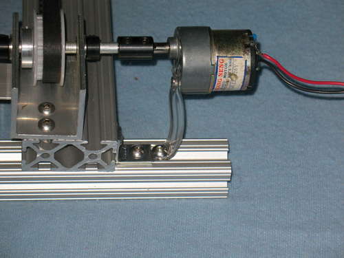
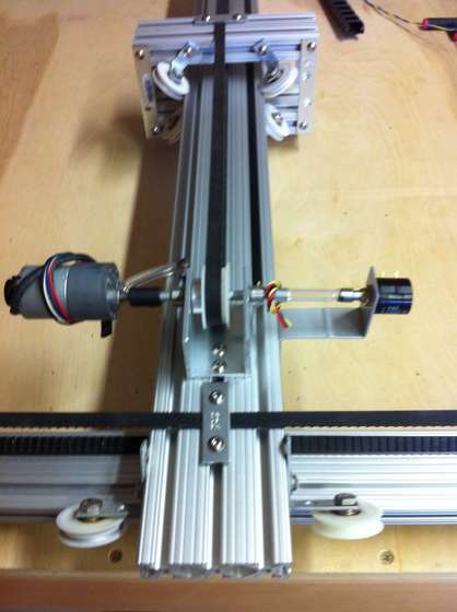
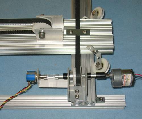
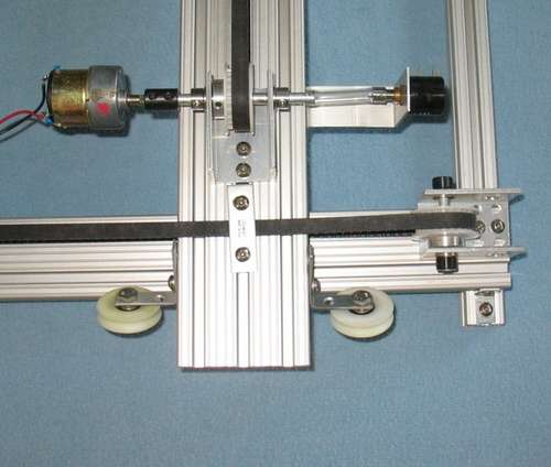
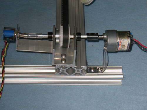
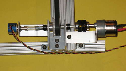
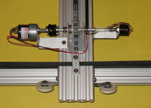
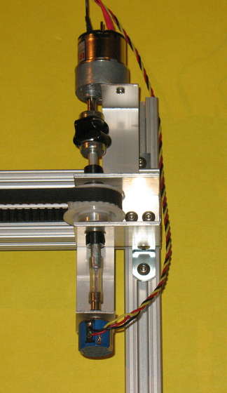
The motors are attached to the 1/4" shaft collars. Since the motors have a 6mm shaft, it's pretty close. To keep the motors from spinning, we loosely attached them with some plastic tubing to allow the motors to move around, which they do a lot. We used 3/6" inside diameter x 5/16" outside diameter tubing.
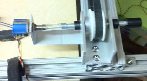
An alternate mounting approach is to make brackets for the motors from some scrap aluminum (we used 1" wide by 1/6" thick), and used flexible shaft couplings. See the pictures for both mounting techniques. These brackets were 4" long and folded to 90 degrees at the 2.5" point along the length. Both mounting approaches worked fine for our application, though the flexible shaft couplers are a bit tighter for CNC type applications.
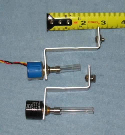
As with the previous project, we used 10-turn potentiometers. They are 5K ohms like those used in hobby servos. With the JRK, we were able to try a few brands to see how they did, and the two that we tested seemed pretty similar. The ETI MH22B series ones are almost $100 now (they were less when we got them), and Bourns 3540 series are around $20. We've seen others at around $10, but have not tested them thoroughly. We got the ETI MH22B series ones before when we were concerned about the lifetime - they are rated at 10 million turns, while most of the others are at 1-2 million. We had an issue before with the pot failing, but in retrospect, that was due to the fixed mechanical mounting, and the short piece of plastic tubing connecting the potentiometers to the shafts fixes that issue, so the less expensive potentiometers should be fine. So, get the less expensive ones and save some money.
For the two we tested, they both showed the full range and detail on the JRK - 0 to 4095 steps, and we could get them to move in one-unit steps, though for many locations, the value would oscillate by one unit. Over the 29.25" travel of the X axis, we got abut 2678 units (pre-calibration) of movement (since it's ~6.66 turns of the timing belt pulley - less than the full 10-turn range), so the precision is theoretically 0.01". If you assume we get half that with the occasional one unit oscillation, it would be around 0.02" (1339 units). In practice, it's probably not that precise.
An interesting comparison: The stepper motor we tried has 1.8 degree full steps, so at about 6.66 revolutions, that's 1332 steps - about the same as the approach we are using. Microstepping would theoretically get higher precision, but we are not sure what the limits are on the mechanics etc.
For the Potentiometers, we made some brackets from some scrap 1" wide aluminum (1/6" thick). To prevent wear on the potentiometer bearings, we used some 3/16" ID x 5/16 OD plastic tubing to connect them to the shafts. See the pictures for the bracket spacing.
Here's a sample video of a stepper motor on the Y Axis. The X Axis needs more power since it needs to move the whole Y Axis too.
Intro | 1 | 2 | 3 | 4 | 5 | 6 | 7 | 8 | 9